Accendisigari elettronico 85A Mosfet Load 85N03
$0.299≥1000Piece/Pieces
| Tipo di pagamento: | L/C,T/T,Paypal |
| Incoterm: | FOB,CFR,CIF |
| Quantità di ordine minimo: | 1000 Piece/Pieces |
| Trasporti: | Ocean,Air |
| Porta: | Shanghai |
$0.299≥1000Piece/Pieces
| Tipo di pagamento: | L/C,T/T,Paypal |
| Incoterm: | FOB,CFR,CIF |
| Quantità di ordine minimo: | 1000 Piece/Pieces |
| Trasporti: | Ocean,Air |
| Porta: | Shanghai |
Modello: YZPST-85N03
marchio: YZPST
| Unità vendibili | : | Piece/Pieces |
| Tipo pacchetto | : | 1. Imballaggio anti-elettrostatico 2. Scatola di cartone 3. Imballaggio protettivo in plastica |
Accendisigari elettronico Mosfet
YZPST-85N03
85A Accendisigari elettronico Mosfet Load Switch Mosfet 85N03
|
VDSS30V RDS(ON) 2.3mΩ(max.)@ VGS=10V RDS(ON) 3.0mΩ(max.)@ VGS=4.5V ID 85A |
|
|
Description |
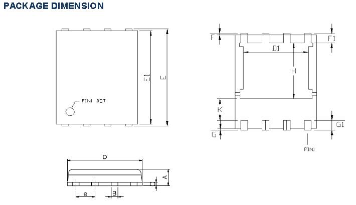
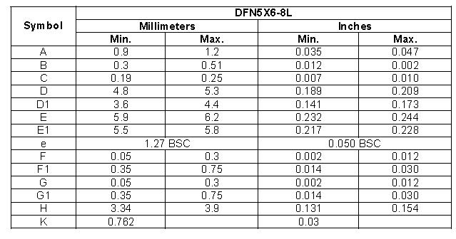
DFN5X6-8L |
|
YZPST85N03 uses advanced Trench technology and designs to provide excellent RDS(ON) with low gate charge. This device is suitable for use in PWM, load switching and general purpose applications. |
|
|
Applications |
Features |
|
■ Lithium-Ion Secondary Batteries ■ Load Switch ■ DC-DC converters and Off-line UPS |
■ Low On-Resistance ■ Low Input Capacitance ■ Low Miller Charge ■ Low Input / Output Leakage |
|
Absolute Maximum Ratings (TA=25°C unless otherwise noted) |
|||
|
Parameter |
Symbol |
Value |
Unit |
|
Drain-Source Voltage |
VDSS |
30V |
V |
|
Gate-Source Voltage |
VGSS |
±20V |
V |
|
Drain Current-Continuous @ TC=25℃ NOTE 3 |
ID |
85 |
A |
|
Drain Current-Continuous @ TC=100℃ NOTE 3 |
68 |
A |
|
|
Drain Current-Pulsed NOTE 1 |
IDM |
320 |
A |
|
Avalanche Current, L=0.1mH |
IAS |
50 |
A |
|
Avalanche Energy, L=0.1mH |
EAS |
125 |
mJ |
|
Maximum Power Dissipation @ TC=25℃ |
PD |
60 |
W |
|
Maximum Power Dissipation @ TA=25℃ |
5.7 |
W |
|
|
Storage Temperature Range |
TSTG |
-50 to 150°C |
°C |
|
Operating Junction Temperature Range |
TJ |
-50 to 150°C |
°C |
|
Thermal Resistance Ratings |
||||||
|
Parameter |
Symbol |
Conditions |
Min. |
Typ. |
Max. |
Unit |
|
Maximum Junction-to-Ambient NOTE2 |
RθJA |
Steady State |
- |
- |
22 |
°C/W |
|
Maximum Junction-to-Case |
RθJC |
Steady State |
- |
- |
2.1 |
°C/W |
|
Electrical Characteristics(TJ=25°C unless otherwise noted) |
||||||
|
Parameter |
Symbol |
Conditions |
Min. |
Typ. |
Max. |
Unit |
|
OFF CHARACTERISTICS |
||||||
|
Drain-Source Breakdown Voltage |
BVDSS |
VGS=0V , IDS=250uA |
30 |
- |
- |
V |
|
Zero Gate Voltage Drain Current |
IDSS |
VDS=30V, VGS=0V |
- |
- |
1 |
uA |
|
Gate-Source Leakage Current |
IGSS |
VGS=±20V , VDS=0V |
- |
- |
±100 |
nA |
|
ON CHARACTERISTICS |
||||||
|
Gate Threshold Voltage |
VGS(TH) |
VGS=VDS, IDS=250uA |
1.2 |
- |
2.5 |
V |
|
Drain-Source On-Resistance |
RDS(ON) |
VGS=10V , IDS=16A |
- |
1.75 |
2.3 |
mΩ |
|
VGS=4.5V , IDS=16A |
- |
2.6 |
3.0 |
|||
|
DYNAMIC CHARACTERISTICS |
||||||
|
Input Capacitance |
Ciss |
VDS=10V, VGS=0V, f=1MHz |
- |
5910 |
- |
pF |
|
Output Capacitance |
Coss |
- |
725 |
- |
||
|
Reverse Transfer Capacitance |
Crss |
- |
537 |
- |
||
|
SWITCHING CHARACTERISTICS |
||||||
|
Turn-On Delay Time |
Td(on) |
VDS=15V, VGS=10V, ID=1A , RGEM=3.3Ω |
- |
20 |
- |
ns |
|
Rise Time |
tr |
- |
6.5 |
- |
||
|
Turn-Off Delay Time |
Td(off) |
- |
122 |
- |
||
|
Fall Time |
tf |
- |
15 |
- |
||
|
Total Gate Charge at 4.5V |
Qg |
VDS=15V, IDS=16A, VGS=10V |
- |
54 |
- |
nC |
|
Gate to Source Gate Charge |
Qgs |
- |
18 |
- |
||
|
Gate to Drain "Miller" Charge |
Qgd |
- |
20.5 |
- |
||
|
SWITCHING CHARACTERISTICS |
||||||
|
Drain-Source Diode Forward Voltage |
VSD |
VGS=0V, IS=4A |
- |
- |
1.3 |
V |
|
Body Diode Reverse Recovery Time |
trr |
If=10A, dl/dt=100A/μs, TJ=25°C |
- |
46 |
- |
ns |
|
Body Diode Reverse Recovery Charge |
Qrr |
- |
38 |
- |
nC |
|
Gli appunti:
1. Test degli impulsi: larghezza dell'impulso ≦ 300μs, ciclo di lavoro ≦ 2%.
2. RΘJA è la somma della resistenza termica da giunzione a caso e da caso a ambiente in cui il riferimento termico del caso è definito come la superficie di montaggio della saldatura dei perni di drenaggio. RΘJC è garantito dalla progettazione mentre RΘCA è determinato dal design della scheda dell'utente. RΘJA mostrato di seguito per il funzionamento di un singolo dispositivo su FR-4 in
ancora aria.
3. La massima corrente nominale è limitata dal pacchetto.


Privacy statement: Your privacy is very important to Us. Our company promises not to disclose your personal information to any external company with out your explicit permission.

Fill in more information so that we can get in touch with you faster
Privacy statement: Your privacy is very important to Us. Our company promises not to disclose your personal information to any external company with out your explicit permission.