Convertitore CC-CA TO-247 Transistori NPN complementari
Ottieni l'ultimo prezzo| Tipo di pagamento: | L/C,T/T,Paypal |
| Incoterm: | FOB,CFR,CIF |
| Trasporti: | Ocean,Air |
| Porta: | Shanghai |
| Tipo di pagamento: | L/C,T/T,Paypal |
| Incoterm: | FOB,CFR,CIF |
| Trasporti: | Ocean,Air |
| Porta: | Shanghai |
Modello: YZPST-2SDW100
marchio: YZPST
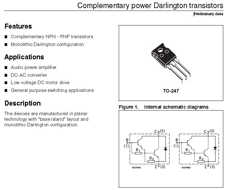
Transistor Darlington di potenza complementare
YZPST-2SDW100
Caratteristiche
■ Transistori NPN - PNP complementari
■ Configurazione monolitica di Darlington
applicazioni
■ Amplificatore di potenza audio
■ Convertitore DC-AC
■ Azionamento del motore CC a bassa tensione
■ Applicazioni di commutazione di uso generale
Descrizione
I dispositivi sono realizzati in tecnologia planare con layout [isola base "e configurazione monolitica Darlington.
T a b le 1 . D e v i c e s ummario
|
Order code |
Marking |
Package |
Packaging |
|
2SDW100 |
2SDW100 |
TO-247 |
Tube |
|
2SDW200 |
2SDW200 |
1 assoluto maxi m un giudizi
T a b le 2 . Ab s o l ut e m a x i m u m ra ti ng
|
Symbol |
Parameter |
Value |
Unit |
|
|
NPN |
2SDW100 |
|||
|
PNP |
2SDW200 |
|||
|
VCBO |
Collector-emitter voltage (IE = 0) |
80 |
V |
|
|
VCEO |
Collector-emitter voltage (IB = 0) |
80 |
V |
|
|
IC |
Collector current |
25 |
A |
|
|
ICM |
Collector peak current (tP < 5 ms) |
40 |
A |
|
|
IB |
Base current |
6 |
A |
|
|
IBM |
Base peak current (tP < 5 ms) |
10 |
A |
|
|
PTOT |
Total dissipation at Tc ≤ 25 °C |
130 |
W |
|
|
TSTG |
Storage temperature |
-65 to 150 |
°C |
|
|
TJ |
Max. operating junction temperature |
150 |
°C |
|
No t e : F o PN P ty p e v olo t un ge e nd c u r r e nt V AL U e s a r e n e g a ti v e
T a b le 3 . T herm al d a ta
|
Symbol |
Parameter |
Value |
Unit |
|
RthJC |
Thermal resistance junction-case max |
0.96 |
°C/W |
2 elettrico c h aratteristiche
T ca s e = 2 5 ° C; salvo che altri ise w spe c ified.
|
|
Symbol |
Parameter |
Test conditions |
Min. |
Typ. |
Max. |
Unit |
|
ICBO |
Collector cut-off current (IE = 0) |
VCE = 80 V |
|
|
0.5 |
mA |
|
ICEV |
Collector cut-off current (VBE = - 0.3 V) |
VCE = 80 V |
|
|
0.1 |
mA |
|
ICEO |
Collector cut-off current (IB = 0) |
VCE = 60 V |
|
|
0.5 |
mA |
|
IEBO |
Emitter cut-off current (IC = 0) |
VEB = 5 V |
|
|
2 |
mA |
|
VCEO(sus) (1) |
Collector-emitter sustaining voltage (IB = 0) |
IC = 50 mA |
80 |
|
|
V |
|
VCE(sat)(1) |
Collector-emitter saturation voltage |
IC = 5 A IB = 20 mA IC = 10 A IB = 40 mA IC = 20 A IB = 80 mA |
|
|
1.2 1.75 3.5 |
V V V |
|
VBE(sat)(1) |
Base-emitter saturation voltage |
C B |
|
|
3.3 |
V |
|
(1) |
Base-emitter voltage |
I = 10 A V = 3 V |
1 |
|
3 |
V |
|
hFE(1) |
DC current gain |
IC = 5 A VCE = 3 V IC = 10 A VCE = 3 V IC = 20 A VCE = 3 V |
600 500 300 |
|
15000 12000 6000 |
|
|
VF(1) |
Diode forward voltage |
IF = 10 A |
|
TBD |
|
V |
|
Is/b |
Second breakdown current |
VCE = 25 V t = 500 ms |
|
TBD |
|
A |
1. Test dell'impulso: durata dell'impulso ≤ 300 μs, duty cycle ≤ 2%.
Per i valori di tensione e corrente di tipo PNP sono negativi.
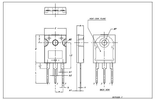
TO- 2 4 7 M e ch a ni c a l dati
|
Dim. |
mm. |
||
|
Min. |
Typ |
Max. |
|
|
A |
4.85 |
|
5.15 |
|
A1 |
2.20 |
|
2.60 |
|
b |
1.0 |
|
1.40 |
|
b1 |
2.0 |
|
2.40 |
|
b2 |
3.0 |
|
3.40 |
|
c |
0.40 |
|
0.80 |
|
D |
19.85 |
|
20.15 |
|
E |
15.45 |
|
15.75 |
|
e |
|
5.45 |
|
|
L |
14.20 |
|
14.80 |
|
L1 |
3.70 |
|
4.30 |
|
L2 |
|
18.50 |
|
|
øP |
3.55 |
|
3.65 |
|
øR |
4.50 |
|
5.50 |
|
S |
|
5.50 |
|


Privacy statement: Your privacy is very important to Us. Our company promises not to disclose your personal information to any external company with out your explicit permission.

Fill in more information so that we can get in touch with you faster
Privacy statement: Your privacy is very important to Us. Our company promises not to disclose your personal information to any external company with out your explicit permission.