Privacy statement: Your privacy is very important to Us. Our company promises not to disclose your personal information to any external company with out your explicit permission.
Solid-state lighting is rapidly becoming the most popular lighting option for a wide range of applications. Due to the US government's task of saving energy, incandescent lamps have been largely eliminated and are increasingly being replaced by light-emitting diode (LED) lamps. The reason is because LED lamps have a longer life (usually 25,000 hours) and can easily accommodate a variety of different socket and shape requirements. As the price of LED lights continues to decline and is becoming more competitive with compact fluorescent lamps (CFLs), it is predicted that the share of LED lighting in the residential lighting market will reach nearly 50% in 2016, 2020 The year will exceed 70%. However, from a designer's point of view, it is important to understand that LED lighting and dimming control present challenges that are different from previous technologies.
Triacs (short for AC triodes) form the core of AC dimming control. These components can conduct current in either direction after triggering (on). In the past, the Triacs used in dimmers were typically designed for incandescent lamp loads and were also dedicated to incandescent lamp loads. The incandescent lamp load has a high current rating under both steady state conditions, a high initial inrush current, and a high inrush current at the end of the filament break life.
In contrast, LEDs have much lower steady-state currents than incandescent lamps, which can have higher initial on-currents for a few microseconds from the beginning of each half cycle of the AC line voltage. Typically, the AC standby lamp has a current spike of 6-8 amps (peak); the steady state continual current is less than 100 mA.
LED lights for home lighting consume 7.5 watts (A19 bulbs, 450 lumens) or higher, while a chandelier typically has four to ten bulbs. However, a string of 50 Christmas lights can consume as little as 4.8 watts. The LED floodlights used in ceiling lamps designed to replace typical filament lighting produce 750 lumens of light and consume only 13 watts (BR 30). In contrast, old filament lighting typically consumes 65 watts.
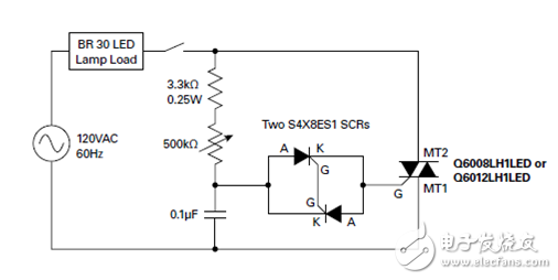
The latest generation of Triacs makes the design of AC circuits used to control LED light output very simple because it requires relatively few components: an ignition/trigger capacitor, a potentiometer, and a voltage breakdown trigger. The use of two anti-parallel sensitive gate thyristors (thyristors) as voltage breakdown triggers enables the control current to produce a wide range of light level outputs. This also allows for lower hysteresis control because the two thyristors form a full anti-breakdown trigger. Figure 1 shows the control circuit diagram for a ceiling light (such as a BR30 LED).

Figure 1: Ceiling floodlight dimmer circuit with two reverse parallel sensitive thyristors
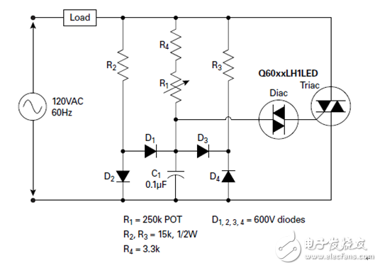
This circuit allows the bulb to be turned on almost 180 degrees per half cycle; remote timing turn-on can also be delayed to a small conduction angle every half cycle for lower light output. Triacs with low hold and lock current characteristics, such as the Q60xxLH1LED series, enable Triacs to be kept at very low current levels. Two anti-parallel, sensitive gate thyristors (S4X8ES1) with sensitive gates connected together produce a very low voltage triggering full reverse breakdown voltage, resulting in very low hysteresis. Thus, the potentiometer can be set for a low conduction angle that is instantly turned on when the line switch is turned off and on. The circuit diagram in Figure 2 shows an improvement to the old phase control/dimmer circuit that provides poor hysteresis by adding a steering diode around the C1 ignition capacitor.

Figure 2: Dimmer circuit design to improve hysteresis.
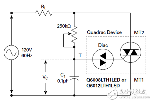
For applications where wide control range and low hysteresis are not critical, Quadrac devices, which combine Diac (a two-terminal AC switching element) and Triac's special thyristor in a single package, provide a simple variable light control method. Figure 3 illustrates how the Diac trigger device and AC Triac can be combined in a single TO-220 stand-alone package to further reduce component count. Due to the higher switching voltage VBO of the Diac trigger device, this control circuit has a lower full turn-on voltage, but dimming is available from 175 degrees to less than 90 degrees per half AC cycle.

Figure 3: In this Quadrac-based dimming circuit, the potentiometer is 250 kΩ with a built-in fixed-end resistance of at least 3 kΩ. The Quadrac device is a QxxxxLTH1LED product with a more sensitive Triac silicon (low gate current and hold current characteristics). RL is the minimum LED load (10 watts). VC is equivalent to the trigger voltage of the built-in Diac silicon.
For more detailed information on LED lighting dimming design, download free application notes from Lite.
About the author: Yoshimoto Yoshihiro is the thyristor business development manager of the semiconductor division of Lite. His responsibilities include finding and developing strategic growth markets and introducing new products into the market for power control products (with a focus on thyristor products). He holds a bachelor's degree in industrial chemical engineering from the University of Tokyo, Japan. He joined Lite in 10 years ago and has been in the electronics industry for 20 years. You can get in touch with him.
August 12, 2024
Mail a questo fornitore
August 12, 2024
December 30, 2020
December 16, 2020

Privacy statement: Your privacy is very important to Us. Our company promises not to disclose your personal information to any external company with out your explicit permission.

Fill in more information so that we can get in touch with you faster
Privacy statement: Your privacy is very important to Us. Our company promises not to disclose your personal information to any external company with out your explicit permission.