Privacy statement: Your privacy is very important to Us. Our company promises not to disclose your personal information to any external company with out your explicit permission.
There are three main dimming methods: analog dimming, PWM dimming, and thyristor dimming. The use of thyristor dimming to dim the LED replacement lamp, the existing dimmer circuit can be unchanged, so the dimming mode is generally optimistic, so there is an AC-DC control chip suitable for thyristor dimming. Infineon's ICL8002G LED driver chip supports TRIAC dimming with single-stage PFC and primary measurement control.
The principle of thyristor dimming
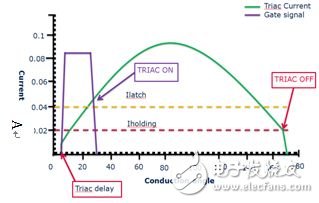
The potentiometer RV2 adjusts the phase angle of the thyristor (TRIAC). When VC3 exceeds the breakdown voltage of the DIAC, the thyristor turns on. When the thyristor current drops below its holding current (Iholding) (see Figure 2 below), the TRIAC turns off and must wait until C3 is recharged in the next half cycle before turning it back on. The voltage and current in the filament of the bulb are closely related to the phase angle of the dimming signal, and the phase angle varies from 0 degrees (nearly 0 degrees) to 180 degrees (depending on the dimmer).
LED dimming problems
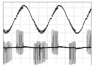
In order for the LED to be dimmable, its power supply must be able to detect the variable phase angle output of the thyristor controller to adjust the current flowing to the LED. It is very difficult to do this while maintaining the dimmer's normal operation, which often leads to poor performance. Problems can be manifested as problems such as flicker and audio noise. These undesirable phenomena are usually caused by factors such as false triggering or premature shutdown of the thyristor. The root cause of false triggering is current oscillations when the thyristor is turned on. Figure 3 illustrates this effect graphically.

Figure 2. Operating conditions for thyristor conduction

Figure 3 SCR current (thyristor is triggered multiple times, but can not maintain conduction)
When the thyristor is turned on, the AC mains voltage is applied almost instantaneously to the LC input filter of the LED lamp power supply. A voltage step applied to the inductor can cause oscillation. If the dimmer current is below the thyristor holding current during the oscillation, the thyristor will stop conducting. The thyristor trigger circuit charges and then turns the thyristor on again. This irregular multiple thyristor restart (Figure 3) allows the LED driver to generate audio noise or LED flicker. Designing a simpler EMI filter helps reduce such unwanted oscillations. For excellent dimming, the input EMI filter inductor and capacitor must be as small as possible.
For thyristors, the holding current required to maintain conduction is typically between 8 mA and 75 mA. Incandescent lamps are easier to maintain at this current level, but for LED lamps that consume only 10% of the equivalent incandescent lamp, this current can be reduced below the thyristor holding current, causing the thyristor to turn off prematurely. This will cause flicker or limit the dimmable range.
August 12, 2024
Mail a questo fornitore
August 12, 2024
August 14, 2023
January 07, 2021

Privacy statement: Your privacy is very important to Us. Our company promises not to disclose your personal information to any external company with out your explicit permission.

Fill in more information so that we can get in touch with you faster
Privacy statement: Your privacy is very important to Us. Our company promises not to disclose your personal information to any external company with out your explicit permission.