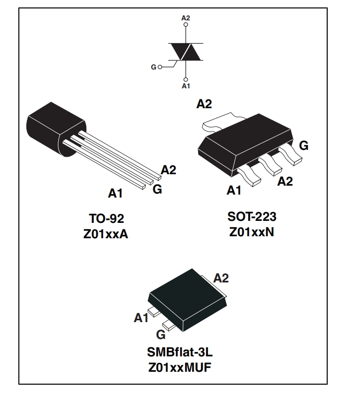
TO-92 TRIACS 1A standard adatti per le applicazioni di commutazione CA per uso generale
$0.033000-29999 Piece/Pieces
$0.02≥30000Piece/Pieces
| Tipo di pagamento: | L/C,T/T,Paypal |
| Incoterm: | FOB,CFR,CIF |
| Trasporti: | Ocean,Land,Express,Others |
| Porta: | SHANGHAI |
$0.033000-29999 Piece/Pieces
$0.02≥30000Piece/Pieces
| Tipo di pagamento: | L/C,T/T,Paypal |
| Incoterm: | FOB,CFR,CIF |
| Trasporti: | Ocean,Land,Express,Others |
| Porta: | SHANGHAI |
Modello: YZPST-Z0103MA
marchio: Yzpst
Luogo D'origine: Cina
IT(RMS): 1A
I²t: 0.35A² s
DI/dt: 20A/µs
IGM: 1A
PG(AV): 1W
Tstg: - 40 to + 150℃
Tj: - 40 to + 125℃
| Unità vendibili | : | Piece/Pieces |
| Tipo pacchetto | : | 1. Packaging antielettrostatico 2. Casella di cartone 3. Braccia |
| Scaricare | : |
|
The file is encrypted. Please fill in the following information to continue accessing it
Standard 1a triacs p/n: yzpst-z0103mn0

| Symbol | Parameter | Value | Unit | ||
| On-state rms current | SOT-223 | T tab = 90 °C | |||
| IT(RMS) | (full sine wave) | TO-92 | TL = 50 °C | 1 | A |
| SMBflat-3L | T tab = 107 °C | ||||
| ITSM | Non repetitive surge peak on-state current (full cycle, Tj initial = 25 °C) | F = 50 Hz | t = 20 ms | 8 | A |
| F = 60 Hz | t = 16.7 ms | 8.5 | |||
| I²t | I²t Value for fusing | tp = 10 ms | 0.35 | ² | |
| A s | |||||
| dI/dt | Critical rate of rise of on-state current IG = 2 x I GT , tr ≤ 100 ns | F = 120 Hz | Tj = 125 °C | 20 | A/µs |
| IGM | Peak gate current | tp = 20 µs | Tj = 125 °C | 1 | A |
| PG(AV) | Average gate power dissipation | Tj = 125 °C | 1 | W | |
| Tstg | Storage junction temperature range | - 40 to + 150 | °C | ||
| Tj | Operating junction temperature range | - 40 to + 125 | |||
Tabella 2. Elettrica caratteristiche ( T j = 25 ° C, salvo che Altrimenti specificato )
| Symbol | Z01 | |||||||
| Test conditions | Quadrant | 3 | 7 | 9 | 10 | Unit | ||
| I GT (1) | VD = 12 V, | I - II - III | MAX. | 3 | 5 | 10 | 25 | mA |
| RL = 30 Ω | IV | 5 | 7 | 10 | 25 | |||
| VGT | ALL | MAX. | 1.3 | V | ||||
| VD = VDRM, | ||||||||
| VGD | RL = 3.3 kΩ, | ALL | MIN. | 0.2 | V | |||
| Tj = 125 °C | ||||||||
| IH (2) | IT = 50 mA | MAX. | 7 | 10 | 10 | 25 | mA | |
| IL | IG = 1.2 I GT | I - III - IV | MAX. | 7 | 10 | 15 | 25 | mA |
| II | 15 | 20 | 25 | 50 | ||||
| dV/dt (2) | VD = 67% V DRM gate open Tj = 110 °C | MIN. | 10 | 20 | 50 | 100 | V/µs | |
| (dV/dt)c | (dI/dt)c = 0.44 A/ms, | MIN. | 0.5 | 1 | 2 | 5 | V/µs | |
| -2 | Tj = 110 °C | |||||||
1. Minimo IO Gt È garantita alle 5% Di I GT max .
2. Per entrambe le polarità di A2 referenziato A A1.
Tabella 3. Caratteristiche statiche
| Symbol | Test conditions | Value | Unit | ||
| VTM(1) | ITM = 1.4 A, tp = 380 µs | Tj = 25 °C | MAX. | 1.6 | V |
| V to (1) | Threshold voltage | Tj = 125 °C | MAX. | 0.95 | V |
| Rd (1) | Dynamic resistance | Tj = 125 °C | MAX. | 400 | mΩ |
| I DRM | V DRM = VRRM | Tj = 25 °C | MAX. | 5 | µA |
| IRRM | Tj = 125 °C | 0.5 | mA | ||
1. Per entrambe le polarità di A2 referenziato A A1.
Tabella 4. Resistenza termica es
| Symbol | Parameter | Value | Unit | |||
| Rth(j-t) | Junction to tab (AC) | SOT-223 | 25 | |||
| Rth(j-t) | Junction to tab (AC) | SMBflat-3L | 14 | |||
| Rth(j-I) | Junction to lead (AC) | TO-92 | 60 | |||
| S(1) = 5 cm² | SOT-223 | MAX. | 60 | °C/W | ||
| Rth(j-a) | Junction to ambient | SMBflat-3L | 75 | |||
| TO-92 | 150 | |||||
1. S = rame superficie Sotto scheda .


Privacy statement: Your privacy is very important to Us. Our company promises not to disclose your personal information to any external company with out your explicit permission.

Fill in more information so that we can get in touch with you faster
Privacy statement: Your privacy is very important to Us. Our company promises not to disclose your personal information to any external company with out your explicit permission.