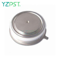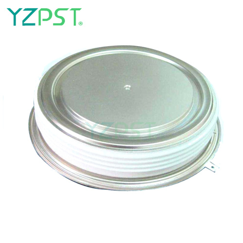
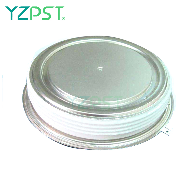
Tiristore inverter ad alta potenza C458PB
Ottieni l'ultimo prezzo| Tipo di pagamento: | L/C,T/T,Paypal |
| Incoterm: | FOB,CFR,CIF |
| Trasporti: | Ocean,Air |
| Porta: | SHANGHAI |

| Tipo di pagamento: | L/C,T/T,Paypal |
| Incoterm: | FOB,CFR,CIF |
| Trasporti: | Ocean,Air |
| Porta: | SHANGHAI |
Modello: YZPST-C458PB
marchio: YZPST
| Tipo pacchetto | : | 1. Imballaggio antielettrostatico 2. Scatola di cartone 3. Imballaggio protettivo in plastica |
Tiristore ad alta potenza
YZPST-DCR1020SF65-1
applicazione di tiristori controllo tiristore motore a corrente continua tiristore Dispositivo montato a tiristori Tutti i valori nominali sono specificati per Tj = 25 oC, se non diversamente indicato.
(1) Tutti i valori nominali di tensione sono specificati per una forma d'onda sinusoidale applicata 50Hz / 60zHz nell'intervallo di temperatura da -40 a +125 oC.
(2) 10 msec. max. larghezza di impulso
(3) Valore massimo per Tj = 125 oC.
(4) Valore minimo per forma d'onda lineare ed esponenziale fino all'80% di VDRM. Cancello aperto. Tj = 125 oC.
(5) Valore non ripetitivo.
(6) Il valore di di / dt è stabilito conformemente alla norma EIA / NIMA RS-397, sezione 5-2-2-6. Il valore definito sarebbe in aggiunta
zione rispetto a quella ottenuta da un circuito di snubber, comprendente un condensatore da 0,2 F e una resistenza di 20 ohm in parallelo con il resistore in prova.
Caratteristiche:. Tutta la struttura diffusa . Center Amplifying Gate Configuration . Capacità di blocco fino a 4200 volt
. Tempo di spegnimento massimo garantito . Alta capacità dV / dt . Dispositivo assemblato a pressione

|
Parameter |
Symbol |
Min. |
Max. |
Typ. |
Units |
Conditions |
|
Average value of on-state current |
IT(AV) |
|
640 |
|
A |
Sinewave,180o conduction,T =60oC c |
|
RMS value of on-state current |
ITRMS |
|
1005 |
|
A |
Nominal value |
|
Peak one cPSTCle surge (non repetitive) current |
ITSM |
|
-
8.5 |
|
KA KA |
8.3 msec (60Hz), sinusoidal wave- shape, 180o conduction, T = 125 j oC 10.0 msec (50Hz), sinusoidal wave- shape, 180o conduction, T = 125 j oC |
|
I square t |
I2t |
|
0.36x10⁶ |
|
A2s |
8.3 msec and 10.0 msec |
|
Latching current |
IL |
|
600 |
|
mA |
VD = 24 V; RL= 12 ohms |
|
Holding current |
IH |
|
200 |
|
mA |
VD = 24 V; I = 2.5 A |
|
Peak on-state voltage |
VTM |
|
3.6 |
|
V |
ITM = 1800 A; Duty cPSTCle 0.01%; T = 25 oC j |
|
Critical rate of rise of on-state current (5, 6) |
di/dt |
|
- |
|
A/ s |
Switching from VDRM 1000 V, non-repetitive |
|
Critical rate of rise of on-state current (6) |
di/dt |
|
100 |
|
A/ s |
Switching from VDRM 1000 V |
E L E CTR I C A L CH A R A C T E R IS T I C S A N D R A T I N G S
|
G a t i n g
|
Parameter |
Symbol |
Min. |
Max. |
Typ. |
Units |
Conditions |
|
Peak gate power dissipation |
PGM |
|
150 |
|
W |
tp = 40 us |
|
Average gate power dissipation |
PG(AV) |
|
5 |
|
W |
|
|
Peak gate current |
IGM |
|
- |
|
A |
|
|
Gate current required to trigger all units |
IGT |
|
- 300 - |
|
mA mA mA |
V = 6 V;R = 3 ohms;T = -40 oC D L j V = 6 V;R = 3 ohms;T = +25 oC D L j V = 6 V;R = 3 ohms;T = +125oC D L j |
|
Gate voltage required to trigger all units |
V |
|
- 3.0 - |
|
V V V |
V = 6 V;R = 3 ohms;T = -40 oC D L j V = 6 V;R = 3 ohms;T = 0-125oC D L j VD = Rated VDRM; RL = 1000 ohms; T = + 125 oC j |
|
Peak negative voltage |
VGRM |
|
5 |
|
V |
|
D y n a m i c
|
Parameter |
Symbol |
Min. |
Max. |
Typ. |
Units |
Conditions |
|
Delay time |
td |
|
- |
0.5 |
s |
ITM = 50 A; VD = Rated VDRM Gate pulse: VG = 20 V; RG = 20 ohms; tr = 0.1 s; tp = 20 s |
|
Turn-off time (with VR = -50 V) |
tq |
|
- |
600 |
s |
ITM = 1000 A; di/dt = 25 A/ s; VR -50 V; Re-applied dV/dt = 20 V/ s linear to 80% VDRM; VG = 0; T = 125 oC; Duty cPSTCle j 0.01% |
|
Reverse recovery charge |
Qrr |
|
* |
|
C |
ITM = 1000 A; di/dt = 25 A/ s; VR -50 V |
* F o r gu un r a n t eed m a x . v a lu e , c on t a c t f a c t o r y .
T H E R M A L A N D ME CH A N I C A L CH A R A C T E R IS T I C S A N D R A T I N G S
|
Parameter |
Symbol |
Min. |
Max. |
Typ. |
Units |
Conditions |
|
Operating temperature |
Tj |
-40 |
+125 |
|
oC |
|
|
Storage temperature |
Tstg |
-40 |
+125 |
|
oC |
|
|
Thermal resistance - junction to case |
R (j-c) |
|
0.022 0.052 |
|
o C/W |
Double sided cooled Single sided cooled |
|
Thermal resistamce - case to sink |
R (c-s) |
|
0.004 0.008 |
|
o C/W |
Double sided cooled * Single sided cooled * |
|
Thermal resistamce - junction to sink |
R (j-s) |
|
- - |
|
o C/W |
Double sided cooled * Single sided cooled * |
|
Mounting force |
P |
18 |
22 |
|
kN |
|
|
Weight |
W |
|
|
- |
g |
|
* M ou n t i ng s ur f a c es s m oo t h, f l a t e g r e a s ed
SCHEMA E DIMENSIONI DEL CASO


Numero Di Telefono: 86-514-87782298
Whatsapp: +8613805278321
Azienda Indirizzo: 3rd Floor, Weiheng Building No.20 B Area, Yangzhou, Jiangsu China
sito web: https://it.yzpst.com


Privacy statement: Your privacy is very important to Us. Our company promises not to disclose your personal information to any external company with out your explicit permission.
Fill in more information so that we can get in touch with you faster
Privacy statement: Your privacy is very important to Us. Our company promises not to disclose your personal information to any external company with out your explicit permission.